
The FCC power mask is set as output power from the antenna, so adding directivity to the antenna means you need to reduce the output power correspondingly. Getting everything just right is hard, but you can tweak it on the VNA.įinally, there are legal issues. When building this, it helps a lot to have a Vector Network Analyzer.
TRIPLE BIQUAD WIFI ANTENNA SOFTWARE
You can model the actual fields with the right software and or analytical calculus. This should help you understand what's happening. (Remember how the ground plane spacing was nominal? It needs to be adjusted to match impedance.) The input impedance depends on the geometry, including the feed points and the distance between the ground plane vis a vis the wire diameter. So 8 dipoles worth of power are directed outward. There's and identical antenna set with orthogonal polarization. That's a total of 4 ½ wave dipoles.īut that's only the signal polarized in one direction. This adds up to two identical ½ dipoles in phase for each of the two squares. In addition it will see an opposing image current off the ground plane, again 90º (nominally anyway) out of phase. But these opposing currents are 90º out of phase.

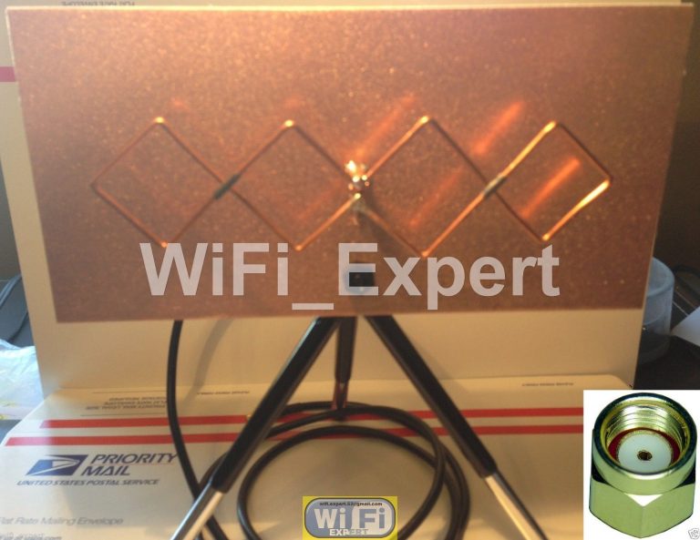
(The overall wave will combine phases from the two directions, but we will only look at one.)Ī point far from the antenna will see the positive current (which is made of accelerating electrons) and the exact opposite current. Thus only the legs in the same direction add phases to signals at one polarity. This happens in both squares of the bow tie shape. It then goes negative and back to 0 at the ground feed. The current is maximum at the end of the first leg, and zero again at the end of the bow. So at t=0, there is no current at the feed point. The center conductor is attached to ½ of the center, and the ground is attached to the other, the post, and the ground plane. Typically they are fed from the center of the tie with an unbalanced coax cable. The antenna is a pair of squares of wire above a ground plane. Understanding these principles, lets look at the Biquad: Mismatching impedance causes energy to reflect back to the power supply, causing problems.

So the antenna typically needs to have an input impedance of 50Ω. Transmission lines can be any impedance, but 50Ω is typical.
TRIPLE BIQUAD WIFI ANTENNA FREE
It acts as an impedance transformer between the transmission line and free space. This adds up to a half wave which makes a good antenna.įinally, an antenna attaches to a transmission line. For example a quarter wave dipole creates another quarter wave in the ground plane like a mirror. This image current can be used to adjust the electrical length of an antenna. The negative charge of the electron draws a corresponding positive charge which exactly matches the electron's movement. An image current is caused in a conductor when electrons (or other charges) move near it. Something called image current also exists. There is a principle called reciprocity which states that antennas which emit well also receive well. But an antenna that is ½ wavelength long has all the current adding part of the time. For every electron moving one way, there's another going the opposite way.
TRIPLE BIQUAD WIFI ANTENNA FULL
Thus an "antenna" a full wavelength long has an average phase of 0º and doesn't emit many photons. Since the EM field is a gauge field, phase matters.


 0 kommentar(er)
